What is Boolean Algebra?
Boolean Algebra, named after the mathematician George Boole, is a branch of algebra that operates on binary values (0s and 1s). Unlike traditional algebra that deals with numbers, Boolean Algebra works with only two values, often represented as True or False, 1 or 0. This unique aspect of Boolean Algebra has made it the backbone of digital electronics, computer science, and logical reasoning, forming the fundamental principles used in modern computing, digital circuit design, and programming.
Table of Contents
ToggleOrigins of Boolean Algebra
George Boole developed Boolean Algebra in the mid-19th century to formalize logical thought using algebraic principles. His work laid the groundwork for expressing logical statements mathematically, allowing for an algebraic approach to logic problems. Later, in the 20th century, Boolean Algebra was found to have critical applications in electrical engineering, particularly with Claude Shannon, who applied Boolean logic to analyze and design relay circuits. This breakthrough eventually led to the creation of digital computers and integrated circuits.
Basic Concepts and Terminology in Boolean Algebra
Boolean Algebra differs from conventional algebra because it operates within a binary system. To fully understand it, we need to break down its core concepts:
- Binary Values: The only two values used in Boolean Algebra are 0 and 1. In logical terms, 0 represents False (off), and 1 represents True (on).
- Boolean Variables: Variables in Boolean Algebra can only take on values of 0 or 1. For example, let AAA, BBB, and CCC be Boolean variables. Each can either be 0 or 1 at any point in time.
- Logical Operations: There are three primary operations in Boolean Algebra: AND, OR, and NOT. Each operation has its unique properties and rules:
- AND (Conjunction): Symbolized by a dot⋅ (or sometimes by simply writing terms side by side like ABABAB), the AND operation outputs 1 if both operands are 1; otherwise, it outputs 0.
- OR (Disjunction): Symbolized by +, the OR operation outputs 1 if at least one operand is 1; if both operands are 0, it outputs 0.
- NOT (Negation): Symbolized by a bar over the variable (e.g., A‾) or an apostrophe (e.g., A′), the NOT operation inverts the value. If the input is 1, the output is 0, and vice versa.
- Truth Tables: A truth table represents all possible combinations of input values and their corresponding output for a Boolean function. Truth tables are essential for analyzing Boolean functions and understanding circuit behavior.
Fundamental Laws of Boolean Algebra
Boolean Algebra is governed by a set of laws and properties that simplify logical expressions. Here are some of the most important ones:
-
Boolean Identity Laws:
- A+0=A
- A⋅1=A
The Identity Laws state that adding 0 to a value or multiplying a value by 1 does not change the original value.
-
Boolean Null Laws:
- A+1=1
- A⋅0=0
The Null Laws express that any variable ORed with 1 is always 1, and any variable ANDed with 0 is always 0.
-
Boolean Idempotent Laws:
- A+A=A
- A⋅A=A
The Idempotent Laws state that combining a variable with itself using AND or OR leaves the original variable unchanged.
-
Boolean Complement Laws:
- A+A‾=1
- A⋅A‾=0
The Complement Laws indicate that a variable ORed with its complement is 1, and a variable ANDed with its complement is 0.
-
Boolean Commutative Laws:
- A+B=B+A
- A⋅B=B⋅A
The Commutative Laws show that the order of variables in an AND or OR operation does not affect the result.
-
Boolean Associative Laws:
- (A+B)+C=A+(B+C)
- (A⋅B)⋅C=A⋅(B⋅C)
The Associative Laws allow us to regroup variables without changing the output of the expression.
-
Boolean Distributive Laws:
- A⋅(B+C)=(A⋅B)+(A⋅C)
- A+(B⋅C)=(A+B)⋅(A+C)
The Distributive Laws provide rules for distributing AND over OR and vice versa.
-
Boolean Absorption Laws:
- A+(A⋅B)=A
- A⋅(A+B)=A
The Absorption Laws allow us to simplify expressions by “absorbing” terms.
Boolean Algebra Theorems
Two important theorems are extremely used in Boolean algebra; De Morgan’s First law and De Morgan’s second law. These two theorems are used to change the Boolean expression. This theorem helps to reduce the given Boolean expression in the simplified form. These two De Morgan’s laws are used to change the expression from one form to another form. Now, let us talk about these two theorems in detail.
De Morgan’s First Law:
De Morgan’s First Law states that (A.B)’ = A’+B’.
The first law states that the complement of the product of the variables is equal to the sum of their individual complements of a variable.
The truth table that shows the verification of De Morgan’s First law is given as follows:
| A | B | A’ | B’ | (A.B)’ | A’+B’ |
| 0 | 0 | 1 | 1 | 1 | 1 |
| 0 | 1 | 1 | 0 | 1 | 1 |
| 1 | 0 | 0 | 1 | 1 | 1 |
| 1 | 1 | 0 | 0 | 0 | 0 |
The last two columns show that (A.B)’ = A’+B’.
Hence, De Morgan’s First Law is proved.
De Morgan’s Second Law:
De Morgan’s Second law states that (A+B)’ = A’. B’.
The second law states that the complement of the sum of variables is equal to the product of their individual complements of a variable.
The following truth table shows the proof of De Morgan’s second law.
| A | B | A’ | B’ | (A+B)’ | A’. B’ |
| 0 | 0 | 1 | 1 | 1 | 1 |
| 0 | 1 | 1 | 0 | 0 | 0 |
| 1 | 0 | 0 | 1 | 0 | 0 |
| 1 | 1 | 0 | 0 | 0 | 0 |
The last two columns show that (A+B)’ = A’. B’.
Hence, De Morgan’s second law is proved.
The other theorems in Boolean algebra are complementary theorem, duality theorem, transposition theorem, redundancy theorem, and so on. All these theorems are used to simplify the given Boolean expression. The reduced Boolean expression should be equivalent to the given Boolean expression.
Simplification of Boolean Expressions
One of the key applications of Boolean Algebra is simplifying logical expressions. Simplification makes complex circuits more efficient and easier to build. There are several techniques for simplifying Boolean expressions:
- Algebraic Manipulation: Using Boolean laws to reduce expressions by canceling terms, applying identities, and combining like terms.
- Karnaugh Maps (K-Maps): A graphical method used to simplify Boolean expressions. K-Maps group terms in a grid format to identify and eliminate redundancies in expressions.
- Quine-McCluskey Method: A tabular method used for minimizing Boolean functions, especially useful when handling larger numbers of variables.
Example of Boolean Simplification
Consider a Boolean expression for a digital circuit with inputs A, B, and C:
F=(A⋅B)+(A⋅B‾⋅C)+(B⋅C)
Using Boolean simplification techniques, we can reduce this expression to a simpler form that requires fewer operations, translating to a more efficient digital circuit.
Applications of Boolean Algebra in Computing
Boolean Algebra’s simplicity and binary nature make it ideal for digital systems, where binary values (0 and 1) directly correspond to the two states in electronic circuits (off and on). Some major applications include:
- Digital Circuit Design: Boolean expressions model the behavior of digital circuits. The simplification of Boolean expressions helps design efficient circuits with fewer components, reducing power consumption and cost.
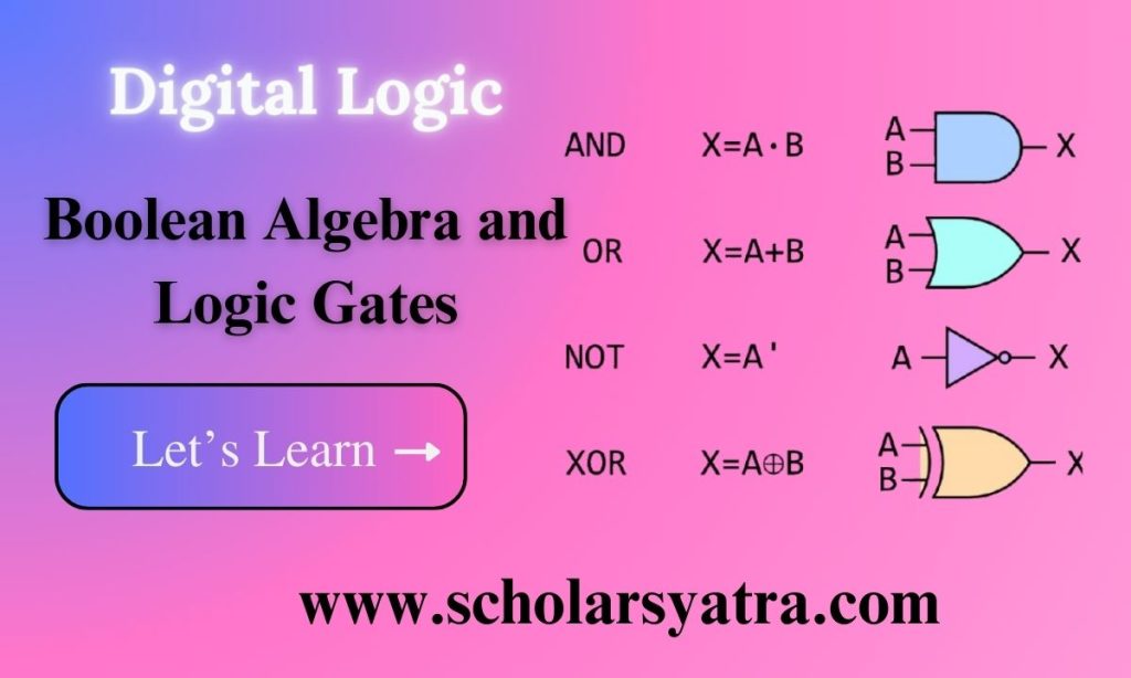
- Logic Gates: The basic operations of Boolean Algebra correspond directly to physical electronic components called logic gates (AND, OR, NOT). These gates are the building blocks of all digital circuits and are used to perform operations in computers, calculators, and more.
- Programming: Boolean logic underlies many programming structures, such as conditional statements and loops. Logical operations and Boolean expressions are essential in controlling program flow.
- Data Search and Filtering: Boolean Algebra helps create complex search queries and filtering mechanisms. In databases and search engines, Boolean operators (AND, OR, NOT) allow users to refine search results based on multiple conditions.
Logic gates are fundamental components in digital electronics that perform basic logical operations on one or more binary inputs to produce a single binary output. These gates work using Boolean Algebra, a form of algebra dealing with true (1) and false (0) values. The combination of various logic gates creates circuits that perform complex calculations, process information, and form the foundation of all digital devices, from calculators to supercomputers.
What are Logic Gates?
Logic gates take binary inputs (1 or 0) and apply a specific logical operation to produce an output, also in binary form. Each type of logic gate corresponds to a basic Boolean operation, such as AND, OR, and NOT, which control how the inputs are combined. The physical form of these gates is often found as small components within integrated circuits, allowing millions of them to work together to handle complex processing tasks.
Types of Logic Gates
There are several basic types of logic gates, each representing a different Boolean operation. Let’s discuss each gate in detail:
-
AND Gate
- Symbol: ⋅ or simply adjacency, such as AB
- Boolean Expression: F=A⋅B
- Operation: The AND gate outputs 1 only if both inputs are 1; otherwise, it outputs 0.
- Truth Table:
A B Output (A·B) 0 0 0 0 1 0 1 0 0 1 1 1 An AND gate accepts two input signals. If the two input values for an AND gate are both 1, the output is 1; otherwise, the output is 0. AND gates are used in applications that require all conditions to be met for an action to be triggered. -
OR Gate
- Symbol: +
- Boolean Expression: F=A+B
- Operation: The OR gate outputs 1 if at least one input is 1; it outputs 0 only if both inputs are 0.
- Truth Table:
A B Output (A+B) 0 0 0 0 1 1 1 0 1 1 1 1 If the two input values are both 0, the output value is 0; otherwise, the output is 1. OR gates are common in circuits where an action can be triggered by multiple conditions. -
NOT Gate
- Symbol: ¬ or overline (e.g., A‾)
- Boolean Expression: F=A‾
- Operation: The NOT gate inverts the input. If the input is 1, the output is 0, and vice versa.
- Truth Table:
A Output (¬A) 0 1 1 0 NOT gates are used to reverse the logical state of an input, essential for toggling conditions in circuits.
-
NAND Gate
- Symbol: AND gate symbol with a small circle on the output (indicating negation)
- Boolean Expression: F=A‾⋅B‾
- Operation: The NAND gate outputs 0 only if both inputs are 1; otherwise, it outputs 1.
- Truth Table:
A B Output (A‾⋅B‾) 0 0 1 0 1 1 1 0 1 1 1 0 NAND gate is the combination of NOT gate and AND gate. If the two input values for an NAND gate are both 1, the output is 0; otherwise, the output is 1. NAND gates are widely used because any Boolean function can be implemented using just NAND gates, making it a “universal gate.”
-
NOR Gate
- Symbol: OR gate symbol with a small circle on the output (indicating negation)
- Boolean Expression: F=A‾+B‾
- Operation: The NOR gate outputs 1 only if both inputs are 0; otherwise, it outputs 0.
- Truth Table:
A B Output (A‾+B‾) 0 0 1 0 1 0 1 0 0 1 1 0 Like NAND gates, NOR gates are also universal and can be used to construct any other gate or logic circuit.
-
XOR Gate (Exclusive OR)
- Symbol: ⊕
- Boolean Expression: F=A⊕B
- Operation: The XOR gate outputs 1 if the inputs are different; it outputs 0 if the inputs are the same.
- Truth Table:
A B Output (A⊕B) 0 0 0 0 1 1 1 0 1 1 1 0 XOR gates are crucial in circuits that require a “difference detection,” such as in binary addition and parity checking.
-
XNOR Gate (Exclusive NOR)
- Symbol: ⊙
- Boolean Expression: F=A‾⊕B‾
- Operation: The XNOR gate outputs 1 if the inputs are the same; it outputs 0 if the inputs are different.
- Truth Table:
A B Output (A‾⊕B‾) 0 0 1 0 1 0 1 0 0 1 1 1 XNOR gates are commonly used in equality detection circuits, where it’s necessary to verify if two inputs match.
Truth Tables in Logic Gates
Truth tables are essential for understanding the behavior of logic gates. Each row in a truth table represents a possible combination of inputs and the corresponding output, providing a clear visualization of how the gate operates under different conditions. Truth tables are fundamental in designing circuits, as they allow engineers to predict and verify circuit behavior before implementation.
Combining Logic Gates to Form Complex Circuits
Logic gates are often combined to create complex digital circuits that perform specific tasks. For instance:
- Adders: A half-adder circuit, built using XOR and AND gates, can add two single-bit binary numbers, outputting a sum and a carry bit. Full adders, which add three bits (two inputs and a carry from a previous addition), are constructed from multiple gates and form the basis of binary arithmetic in digital computers.
- Multiplexers: Multiplexers (MUX) route multiple inputs to a single output based on control signals, created from various AND, OR, and NOT gates.
- Encoders and Decoders: Encoders convert multiple inputs into a binary code, while decoders convert binary input into multiple outputs, used in memory addressing and data transmission.
- Flip-Flops and Latches: Sequential circuits like flip-flops and latches store binary information. They use combinations of NAND and NOR gates to maintain stable output until reset, important for memory and state storage in computing.
Applications of Logic Gates
Logic gates are fundamental to digital electronics and have applications across a wide range of devices and systems:
- Computers and Processors: Logic gates form the core of CPUs, enabling them to execute instructions, perform arithmetic, and make decisions based on conditions.
- Data Transmission: Logic gates are used in encoders, decoders, and error-checking circuits in communication systems.
- Control Systems: Sensors and control devices use logic gates to respond to inputs, turning devices on or off based on specific criteria.
- Digital Displays: Digital clocks, calculators, and other display devices rely on logic gates to convert binary information into readable formats.

